
Tank Blanketing Systems
Tank blanketing systems maintain a slight (0.5″ WC) minimum positive pressure of an inert gas within the vapor space of an enclosed vessel. As most atmospheric storage tanks are only rated at approximately 2″ WC an accurate and reliable maintenance of the minimum pressure is essential to keep the tank from forming a vacuum internally due to stock pump-out or ambient cooling effects.
For over 20 years Appalachian Controls provided “piped up” tank blanketing systems, through their 78, 79, 80 and 90 Series systems, to the chemical, pharmaceutical, food and computer industries.
These systems were designed to be simple, accurate and extremely rugged with minimum life spans of 5-15 years. Using gas field production regulators and wide tolerances, these regulators stood up to heat, cold, dirt and generally rough environmental conditions for years with little or no maintenance.
Several years ago Appalachian Controls obsoleted these “piped up” tank blanketing systems in favor of a newer piston/diaphragm design that has its roots in the Anderson Greenwood blanketing regulator of many years ago. In the past year Fisher has bought Appalachian Controls Environmental (ACE) and are no longer supplying the technical assistance, parts or replacement tank blanketing systems that had brought Appalachian Controls to the forefront of tank blanketing applications. There are literally thousands of the older “piped up” Series 78, 79, 80 and 90 Tank Blanketing Systems still in service around the world and no one to go to for information, replacement parts or new systems.
As a former employee of Appalachian Controls and with a great love and respect for these older systems, I would be interested to help anyone who has one of these “piped up” tank blanketing systems and has a need for technical information, parts or replacement systems. If you have an existing system, please let us know the model number and serial number that is stamped on the tag riveted to the cross bar. The model number identifies the Series and options included on the system. The serial number is a date code: xx(year), xxx(Julian day of the year), x sequential number of units produced that day). Inlet nitrogen pressure, required flow rate (SCFH nitrogen), system set point and tank relief vent settings are also required for replacement systems.
The History of Appalachian Controls
Over 25 years ago, a man named Sam Richard, Jr. worked for, then bought, the South Charleston branch of the Fogleman Company, a Pittsburgh based industrial controls distributor. Sam Jr. was a former engineer for Rust Engineering and then Union Carbide. Being a respected engineer, he had close ties with many other engineers working in the chemical plants of the Kanawha valley. He named his company Appalachian Controls Company. Appalachian Controls became a major industrial supplier of controls and instrumentation. Then one day Union Carbide came to Sam and asked for a simple, reliable tank blanketing system, ready to install in a nitrogen line. They had problems with the Anderson Greenwood systems because of dirt and rust and Fisher would only provide the individual components that the customer would have to assemble and calibrate. Sam put together a regulator package built from the same Rockwell regulators that Appalachian Controls sold. Union Carbide liked the system and incorporated it into their standards (IN22.2).
For several years Appalachian Controls built 40-50 tank blanketing systems a year for various Union Carbide plants around the world. Then one day the area Rockwell rep came into town and said that Rockwell would like to do a news article for their in-house magazine. He was putting Rockwell regulators into the industrial market, and Rockwell liked that. The magazine published and shortly thereafter there came a clamor from around the country for this simple reliable tank blanketing system. Appalachian Controls came onto the national scene as a reliable, economical, knowledgeable supplier of tank blanketing systems. The Union Carbide system became the 78 Series. Soon requests for lower and higher capacity systems brought the 79 and 80 Series into being. Over the years the tank blanketing business grew steadily until, in the early ’90’s, EPA regulations boosted the business considerably. Sam Jr. had passed away in the fall of 1987 from cancer. His son, Sam Richard III now had the business. Appalachian Controls grew to be a world leader in tank blanketing. Custom packages were designed for special applications and a wealth of hard earned knowledge was being accumulated. At around that same time, others saw an opportunity in tank blanketing. Valve Concepts emerged with a small compact system that worked very well.
Soon everyone, including Appalachian Controls, developed their own version of this new, compact style blanketing system. Now there were five where there had once been two or three. Appalachian Controls discontinued the older “piped up” systems in the late ’90’s, and the new system did well. But thousands of the older “piped up” systems remained in service. These old systems were designed to give many years of trouble free service. Now the fleet is getting older and people are asking for replacement systems and parts. But alas, Appalachian Controls sold out to Fisher, and Fisher declared that there will be no more Rockwell regulators or parts sold through its subsidiary. Finally Fisher decided to move the operation from South Charleston, WV to its facility in McKinney, TX. The small crew that hand assembled and tested every system for over 10 years were out of a job. Appalachian Controls was gone. Working for Appalachian Controls was good. The business was small and there was a sense of family within its walls. Bonus’ were shared by everyone if quarterly quotas were exceeded. There was a turkey at Thanksgiving and ham and a bonus at Christmas.
What to do now? Is there a need for the older “piped up” tank blanketing systems Appalachian used to make? We don’t know, but would like to find out. If you are pleased with the older “piped up” systems and need a replacement, technical help or a few replacement parts, please feel free to contact us. If there is enough demand, well, who knows, we just might get back into the business. No one makes this style system any longer.
Installation, Maintenance & Operation Manual: Series 121/78, Series 046/79, Series 461/80, Series 243/90
Preface
This booklet is an update and revision of the original Appalachian Controls Tank Blanketing Installation, Operation & Maintenance Instructions. Appalachian Controls ceased production of their 78, 79 80 & 90 Series, for which this manual was written, systems in the late ‘90’s. We here at Appalachian Blanketing Systems are continuing to build these older style Systems and support them with parts and information. This booklet is part of that information. It is meant to cover some basics, installation, operation and maintenance for both the Appalachian Controls and Appalachian Blanketing Systems tank blanketing systems.
The Appalachian Blanketing Systems series model numbering differs only from the Appalachian Controls’ numbers in regards to the first two digits. The 78 Series is now the 121 Series, the 79 Series is now the 046, the 80 Series is now the 461 Series, and the 90 Series is the 243 Series. We will reference both old and new series in this booklet (i.e., 79/046) as both the old an new models are identical.
We have taken liberty to modify the original text where we needed to clarify, update and correct information. In some areas of text and illustration, we have left them completely intact. The person writing this revision is the same person who wrote it originally in 1990, so some license will be taken to present a more readable, accurate, and correct version.
Thank you,
Appalachian Blanketing Systems
Considerations
The purpose of tank blanketing is to maintain a slightly positive pressure atmosphere of an inert gas in the vapor space of a vessel, in relation to external atmospheric pressure. There are three main reasons why this is desirable for product storage:
A positive pressure prevents the entrance and migration of ambient air into the vessel. The ambient air contains oxygen that can react with the product and moisture that can condense and cause product contamination and rusting of the interior walls of the tank.
The exclusion of the oxygen in the air provides safety by reducing the combustibility of the product and its vapors.
By maintaining a slightly positive pressure, the possibility of a vacuum condition that could collapse the tank is greatly minimized.
The blanket pressure is kept to a minimum to conserve the inert gas, usually nitrogen, which is a purchased product.
The Appalachian Blanketing Systems are typically set to maintain a minimum pressure of between 0.5” WC and 1.0” WC
The Systems normally control within +/- 0.1” WC of set point.
A blanketing system maintains the lower limit of the vessel’s internal pressure. The conservation vent limits the upper end of the vessel’s pressure.
The wider the difference between the lower and upper settings, the greater the savings in gas used.
The blanketing system’s set point should be no higher than 50% of the conservation vent’s pressure setting. Once opened, a weighted pallet tank vent can “simmer” until the vessel’s pressure has fallen below 50% of its opening point.
All gas blanketing systems should be checked periodically to make sure they are performing to specification.
Systems are usually located outdoors, on top of the vessels they are blanketing. Being outdoors they are subject to temperature extremes, precipitation, sun, ozone, product vapors and wind.
They must operate for long periods of time with a tight shut off, but remain sensitive to small pressure changes within the vessel. 3. They must be able to react with large volumes quickly as transfers or sudden temperature drops (rain squalls, pump outs, etc.) occur.
Safety considerations:
Nitrogen, being an inert gas, will not support life when breathed. It is odorless, colorless and tasteless.
Vessel pressure ranges must be known and not exceeded. Design specifications, age, condition of the vessel are all-important considerations.
Tank surfaces can be hazardous during inclement weather. Use the buddy system and safety harnesses.
Some product vapors are extremely dangerous. Be cautious when working around a blanketing system or conservation vent. Know your product and take necessary precautions.
Gas Blanketing System Installation Instructions
General
This System has been assembled, calibrated and tested based on the pressures indicated on the purchase order (supply pressure and set point). It is not necessary to make any adjustments to any of the components, except the Sensing Regulator (C) for fine tuning of the blanket set point. Settings of the System’s various regulators are given on pages 6-7 of this instruction for checking only. Misadjustment of the regulators can easily render the System inoperative. Refer to IOM-04 for precise recalibration instructions.
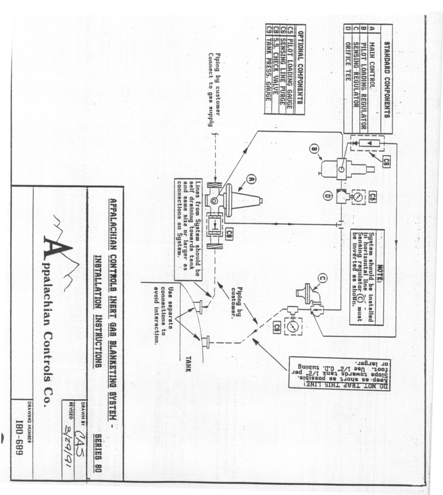
Please refer to the drawing at the end of this section. The standard components are identified with a letter surrounded by parenthesis ( ); optional components are identified with a letter-number combination surrounded by brackets [ ] that refer to the Ordering Information Table of options. The System may incorporate some, all, or none of these options.
Installation
Prior to installation remove all plastic shipping caps (usually 3), give the System a visual for obvious damage and proceed as follows:
Piping
The sensing line from the Sensing Regulator (C) to the tank should be a minimum of 1/2” OD tubing. When running the tubing, take care to avoid any low spots that could create a “trap”. Slope the sensing line a minimum of 1/2” per foot of run towards the vessel, so that the line is self draining into the vessel. If the System does not have the [C9] Pressure Gauge option, a 1/2” tee with the “branch” plugged is advisable for checking the System’s set point and future troubleshooting.
The line from the Main Control Valve (A) to the tank should be the same size, or larger than, the body pipe size of the Main Control Valve.
We recommend that the System be mounted on top of the vessel. If the System is mounted below the top, a “drip leg” should be installed on both the sensing and main lines at their respective lowest points. Install a manual valve at these points to periodically remove any condensate accumulation. Caution: Condensate may be condensed product vapors!
Connect the blanketing gas supply to the System’s 1st Stage Regulator [D], or for Systems without a 1st Stage, directly to the inlet side of the Main Control Valve (A). Supply pressure should be within +/- 10% of the pressure stated on the purchase order (250 PSIG max. on Systems with a 1st Stage Regulator).
It is recommended that a Y type strainer with a 64 mesh screen be installed upstream of the System to remove dirt and scale that might cause internal seating problems.
Orientation
All Systems should be installed in a horizontal pipe run with the regulator diaphragm cases directly above the centerline of the piping and level.
Support
The average Systems weighs between 25-80 lbs. and is normally supported by the inlet and outlet piping runs.
Vessel connections
Both the sensing line and main line tank connections should be made with separate nozzles to avoid any interaction between each other. If main line flow or pressure is “seen” by the sensing line, the System may not function properly. Both connections must be made above the liquid level in the vessel. If the vessel only has one available connection point, a Single Point Connector (SPC) is available as an accessory.
Notes
Care has been exercised to keep the System clean and free from debris. Avoid excessive use of pipe dope. We do not recommend the use of Teflon tape on pipe joints.
When tightening any fitting into the Sensing Regulator (C) body, just “snug” tighten. Over tightening will cause the cast iron body to crack.
Do not weld lines to the System. The bodies of the three regulators are either cast iron or ductile iron, which do not lend themselves well to welding.
For future maintenance, pipe unions should be installed on the inlet, outlet and sensing lines.
Shut off valves installed in the inlet, outlet and sensing lines can be invaluable for servicing and troubleshooting the System. Be sure that the sensing line valve has a minimum 1/2” port.
The sensing line must be free of any restrictions and full diameter along its full length. Any blockage will cause the System to not function correctly, or at all.
If the System has a Sensing Line Purge option [C6], be sure that the purge is turned off before closing any isolation valve on the sensing line. Excessive pressure would build up on the outlet of the Sensing Regulator (C) and cause internal damage.
Start Up
After all piping is complete, start up the System as follows:
Open all valves between the System and the tank (main line and sensing line).
Gradually open the valve supplying gas to the System. In this way pressurization is gradual, not abrupt and the System will have time to reach Pilot Loading pressures. The amount of time will depend on the size of the vessel, normally just a few seconds. Once the System is pressurized and the vessel has reached the blanket set point, this valve should be left wide open.
When starting up a single stage System (80/461 or 90/243), throttle back on the downstream isolation valve about 50% to allow the supply gas to be diverted up to the Pilot Loading Regulator (B). The flow capacities on these two single stage Systems is high enough that the Pilot Loading Regulator may get starved on initial start up.
In some cases the blanket set point will need some fine tuning. Set point changes are made at the Sensing Regulator (C). Remove the spring adjustment cap (on the spring tower pointing down), turn the spring adjustment button in, or clockwise as seen from below, to increase the set point. To decrease the set point, turn the spring button out, or counterclockwise.
The 1st Stage Regulator [D], Main Control Valve (A) and Pilot Loading Regulator (B) are preset and do not require field adjustment. If it is felt that any of these are out of adjustment, compare the values found below and call the factory for assistance before resetting. Values given for the Main Control Valve and Pilot Loading Regulator are as read on the Pilot Loading Gauge [C5]. The 1st. Stage Regulator setting is as read on the Interstage Pressure Gauge [D3].
Old 78 Series, using Rockwell 122 Regulator
Start to close: 8 oz/in2
Full close: 10-12 oz/in2
Newer 78/121 (w/Rockwell 121 Regulator) & 90/243 Series
Start-to-close: 2-1/4 PSIG
Full close: 2.75 PSIG
79/046 & 80/461 Series
Start-to-close: 5-6 PSIG
Full closed: 8-9 PSIG
Old 78 Series (w/122 Rockwell Regulator)
16 oz/in2, 1 PSIG
Newer 78/121 Series (w/121 Rockwell Regulator
3.5-4 PSIG
79/046 & 80/461 Series
10 PSIG
Most Systems: 10 PSIG
Optional Features
Check the System model number, or respective drawing, to determine which options the System is equipped with. The following is a list of standard options available and a description of each.
[C1] Inlet Pressure Gauge — Normally mounted at the inlet of the Pilot Loading Regulator. Indicates inert gas supply pressure to the System.
[C2] SS Orifice in Sensing Regulator — Replaces the standard aluminum orifice with a 316SS orifice.
[C3] SS Main Control Valve Orifice — Replaces standard brass orifice with either a 416 SS or 316 SS orifice.
[C4] SS Tubing Fittings — Replaces standard copper and brass tubing fittings with 316 SS tubing & fittings.
[C5] Pilot Loading Gauge — Indicates pressure downstream of the Orifice Tee (E) that is controlling the throttling of the Main Control Valve (A). Primarily used to observe System operation. Standard on all Systems since 11/91.
[C6] Sensing Line Purge — 0-1 SCFH rotometer used to sweep Sensing Line towards vessel with the blanket gas to keep detrimental tank vapors from entering the Sensing Regulator. Fed from downstream tap on Pilot Loading Regulator. Normally set between ¼ – 1/3 SCFH.
[C7] Main Line Purge — (not shown) has same function as [C6] above, but purges the Main Line from System to vessel.
IMPORTANT | Adjust purge(s) to as low a flow as possible and still maintain a small positive flow from System to vessel, normally 0.2-0.3 SCFH. Do not leave meter valve(s) open at flow rates above 1 SCFH during normal operation. Also, do not close any valving on the Sensing Line while the purge is on. Excessive pressure will build up on the outlet of the Sensing Regulator (C), causing damage to its valve. |
[C8] Outlet Check Valve — A 316 SS & Teflon spring loaded ball check valve mounted to the outlet of the System to keep harmful vapors out of the Main Control Valve (A).
[C9] Tank Pressure Gauge — A low pressure gauge mounted on the outlet of the Sensing Regulator (C). Indicates tank pressure as seen by the Sensing Regulator. Normally supplied with a range from 0” WC through the vessel’s pressure relief vent setting.
[C10] Explosion-proof Pressure Switch — (Not shown) Contains a set of SPDT (form C) dry contacts that can be actuated by vessel pressure or inlet pressure or flow to give a binary output to a remote location.
[C11] SS Main Control Trim — (On Appalachian Blanketing Systems only) Replaces standard brass internal trim with 416 SS or 316 SS trim.
[C12e/v] EPDM or Viton Trim, Sensing Regulator — Replaces standard Buna-N diaphragm, valve and seals with EPDM (e) or Viton (v).
[D1,2] 1st Stage Regulator — Reduces the high pressure initial blanket gas supply pressure to a lower, more controllable level, typically 10 PSIG. This reduced pressure is what the Main Control Valve (A) throttles into the vessel to maintain the blanket pressure.
[D3] Interstage Gauge & Shutoff — Indicates outlet pressure of 1st Stage Regulator [D] and pressure being supplied to Main Control Valve (A). Gauge is 0-30 PSIG range, normally reading 10 PSIG.
[G] Interstage Safety Relief Valve — Provides over-pressure protection for Main Control Valve (A) in the event of a 1st Stage Regulator failure and/or limits maximum pressure flowing into vessel in case of Main Control Valve failing open.
[Sp] Specials — Whenever a System contains a configuration that is not standard, a “SP” is added to the end of the model number. This “SP” can refer to any variation from standard from paint to elastomers to piping arrangements to added components to anything. Refer to the purchase order specification or the factory to determine what the “SP” stands for.
Install Drawings
Maintenance Recommendations
Monthly, or until observation indicates that a more extended period may be used:
Open drain cock on Pilot Loading Regulator (B) condensate bowl and blow off any accumulated moisture.
Visually inspect the System for obvious problems such as external corrosion, damaged tubing, external leaks, bug vents missing or not pointing downwards, etc.
Cycle the System a few times to check for normal operation. Manually, slowly relieve internal tank pressure slowly to see if System maintains vessel pressure at set point.
CAUTIONTank vapors will escape and can be possibly hazardous! Observe tank blanket pressure using [C9] Tank Pressure Gauge option or a manometer. Vessel should be between the System’s set point and the vessel’s relief vent set point. Above the System’s set point the System should be shut off and not flowing any gas.
If tank is above desired set point and flowing, check Pilot Loading Gauge [C5] pressure reading, sensing line for leaks, or Sensing Regulator (C) set point.
If tank is as at, or just below, set point and flowing, check for leaks between the outlet of the System and the tank, other tank connection points and the pressure relief vent.
NOTEMost weighted pallet tank vents do not reseat bubble tight until the vessel pressure has fallen 50% below the vent’s opening set point. If vessel is below the System’s set point and the System is not flowing, check the System’s set point setting, that there is gas to the System, the Pilot Loading pressure ([C5] gauge), blockage between the Sensing Regulator (C) and the tank, and any valves between the System and the tank that might be closed.
After three months, if moisture has been found in the Pilot Loading Regulator, blow off condensate monthly and replace internal filter element as follows:
Shut down and depressurize the System by closing inlet gas supply valve and opening vessel relief vent until Pilot Loading Gauge (C5) reads “0”.
An alternate method is to shut off the supply gas to the System and open the Sensing Line to atmosphere, which should cause the System to go wide open and relieve all internal pressures. After the unit is depressurized, closed the isolation valve between the System and the tank.
Remove Pilot Loading Regulator (B) and disassemble condensate bowl.
Clean bowl and install new filter and o-ring.
Reassemble, making sure bowl gasket/o-ring is positioned correctly.
Remount Pilot Loading Regulator (B) and cycle System several times to ensure correct operation. If spring set point screw has not been disturbed, regulator should still have same set point and not need readjustment.
Annually:
Visually inspect System for external damage/corrosion.
Observe all set points to verify they are within specification. The most critical are the Pilot Loading Pressure and blanket set point settings.
Shut down and depressurize the System
Remove 1st Stage Regulator [D] topworks by loosening union nut between body and diaphragm case and lifting off. Inspect soft seat valve and orifice for wear/debris. Replace as necessary.
Check Main Control Valve (A) valves and orifices,
On 79/046 Systems, remove topworks as done on 1st Stage Regulator [D] above.
On 78/121 Systems, remove the four (4) bolts on the bottom plate and inspect.
On 80/461 Systems, unscrew the two (2) side inspection port covers and inspect.
On 90/243 Systems, remove the four (4) cap screws around the Clamp Ring between the body and diaphragm case and lift off the whole diaphragm case assembly to inspect. (Note: when reassembling, only “snug” the four cap screws. Over tightening will crack the Clamp Ring.
Remove, inspect, clean and reinstall upstream line strainer.
Perform maintenance on Pilot Loading Regulator as detailed in B.2., above.
Reassemble and pressurize up the System.
Use leak detector to check all connections for leaks.
Check all set points per Check-out/Recalibration instructions (IOM-04). Cycle System several times to verify normal operation.
Whenever replacement parts are needed, it is imperative that the System’s model number and serial number are provided. Model number & serial number information located on the name plate riveted to the System’s angle iron cross bar holding the Sensing (C) & Pilot Loading (B) regulators. Over the years some of the components have been revised and/or modified and there may be problems function and/or fit on replacement parts.
We request that whenever problems are encountered in the field with either an older Appalachian Controls, or our current offering, that you notify us. We are continually evaluating the Systems and appreciate comments as to how the Systems are holding up and performing over the long run.
System Operation, Check-out and Recalibration
Overview
To give a description of how the Systems operate.
To give an in-depth field set up for testing and recalibration of a System while installed on a vessel.
To give a field guide for checking & recalibrating Systems while on the tank.
System Operation
Supply gas enters the inlet of the 1st Stage Regulator [D] or inlet of Main Control Valve (A) if no 1st Stage Regulator.
On two stage Systems, the majority of the gas is reduced to, typically, 10 PSIG and sent down the Interstage Piping (L) to the Main Control Valve (A).
A tap on the inlet side of the 1st Stage Regulator [D], or inlet side of the Main Control Valve (A) on single stage Systems, feeds a portion of the supply gas up to the Pilot Loading Regulator (B) via the Pilot Regulator Supply Tube (N).
The Pilot Loading Regulator (B) reduces the inlet pressure to pilot loading pressure for the particular System.
78 Series (w/Rockwell 122 Reg.)
Static set is 28” WC/16 oz/1 PSIG
79/046 & 80/461 Series
Static set is 10 PSIG
90/243 & 78/121 (w/121 Reg.) Series
Static set is 3 PSIG
Reduced pressure pilot loading gas passes through the Orifice Tee (E) (1/4” street tee) on the outlet of the Pilot Loading Regulator (B)
Orifice Tee (E) is 0.06”-0.07” diameter.
If System has purge option(s) (C6/C7), the flow meter is fed from the downstream side tap on the Pilot Loading Regulator, flows through the flow meter and is tapped into the outlet of the Sensing Regulator’s (C) body.
NOTEFrom this point on, all Pilot Loading pressures can be monitored on the [C5] Pilot Loading Gauge.
On initial startup all regulators are normally open, so there is immediately a flow into the vessel. As the vessel’s pressure comes up, tank pressure increases, causing the Sensing Regulator to close off against its seat/orifice. ([C5] Gauge starts at “0” and rises as Main Control Valve (A) closes off.)
With the Sensing Regulator closed, pressure fills the Pilot Loading Tubing (F), backside/underside of the Main Control Valve (A) diaphragm case and to the inlet side of the Sensing Regulator (C).
As the pressure builds in the Main Control Valve’s diaphragm case (Sensing Regulator (C) closed), the diaphragm moves, against a spring on the opposite side of the diaphragm, to close off the Main Control Valve’s seat/valve. These pressures can be read on the [C5] Gauge.
78 Series (w/Rockwell 122 Reg.)
Start-to-close = 7-8 oz./in2
Full close by 12 oz./in2
79/046 & 80/461 Series
Start-to-close = 5-6 PSIG
Full close by 8-9 PSIG
90/243 & 78/121 (w/121 Reg.) Series
Start-to-close = 2-2.25 PSIG
Full close by 2.75 PSIG
When tank pressure falls to, or below, the Sensing Regulator’s (C) set point,
Tank pressure loading the upper side of the Sensing Regulator (C) diaphragm decreases,
The set point spring on the atmospheric side of the diaphragm moves the diaphragm, moving the Sensing Regulator’s valve off its seat (orifice). [C5] Gauge starts to drop.
Because the Sensing Regulator’s orifice is larger than the orifice in the Orifice Tee (E), the pressure in the Pilot Loading Tubing (F) drops, decreasing the pressure in the Main Control Valve’s diaphragm case.
As pressure decreases in the Main Control Valve’s diaphragm case, its set point spring moves the diaphragm, lifting the Main Control’s valve off its seat (orifice).
This allows the blanket gas to flow into the tank, maintaining the tank’s minimum pressure setting.
When the tank pressure rises above the Sensing Regulator’s (C) set point ([C5] gauge rises),
Tank pressure loads the Sensing Regulator’s diaphragm, causing it to move, closing the Sensing Regulator’s valve and orifice. [C5] Gauge rises.
With the Sensing Regulator’s valve closed, gas fed through the Orifice Tee (E) now builds pressure in the Pilot Loading Tubing (F) and the Main Control Valve’s diaphragm case, closing off flow to the tank.
Because we are using variable pressure signals based on vessel pressure, the System’s response is proportional, or throttling, to match the rate of leakage, pump out, or contraction within the vessel. The [C5] Pilot Loading Gauge is an invaluable and excellent tool to watch a System operating and troubleshooting problems.
Set Up for Testing/Troubleshooting
Verify actual supply pressure at inlet of System. If a tap or gauge is not installed near the System’s inlet and the System does not have the Inlet Pressure Gauge option [C1], install a gauge as follows:
Shut off supply gas to System and depressurize System (see IOM-03, B.1.).
Cut Pilot Loading Regulator Supply Tubing (N) and install a compression x female fitting in the line. Fitting should be 3/8”OD x 3/8”OD x 1/4” FNPT.
Install a pressure gauge with a range that is twice the normal supply pressure to the newly installed tee’s 1/4” branch port.
An alternative would be to remove the 3/8”OD x 1/4” MNPT compression fitting from the inlet side of the Pilot Loading Regulator (B), install a 1/4” street tee in it’s place with a new 3/8” OD x 1/4” MNPT compression fitting, shorten the Pilot Regulator Supply Tubing (N) and reconnect to new fitting. The pressure gauge can now installed into the open 1/4” FNPT port of the street tee.
Verify the Pilot Loading Regulator’s (B) set point is set to spec. This is read on the Pilot Loading Pressure Gauge (C5), which has been standard on all Systems for a number of years. If the System does not have one, install one in the branch port (should have a plug) of the Orifice Tee (E). Static setting is highest reading on C5 gauge, Sensing Regulator (C) outlet blocked off or tank pressure well above System set point.
Older 78 Series (w/122 Regulator) Systems
Use 0-32 oz./0-55” WC range gauge
79/046 & 80/461 Series
Use 0-30 PSIG range gauge
90/243 & 78/121 Series (w/121 Regulator) Systems
Use 0-5 PSIG range gauge
Static settings should read:
Older 78 Series (w/122 Regulator)
16 oz/in2 or 1 PSIG
Newer 78/121 (w/121 Regulator) & 90/243 Systems
3.5-4.0 PSIG
79/046 & 80/461 Systems
10 PSIG
Verify actual tank pressure, preferably at the Sensing Regulator (C) outlet port.
If the tank does not have a pressure gauge and the [C9] option has not been ordered with the System, install a Dwyer Magnehelic pressure gauge or manometer with a range not exceeding three (3) times the desired set point.
Cut Sensing Line and insert a 1/2” tee in the line. Use the “run” of the tee to continue the Sensing Line, use the “branch” as the gauge port.
Either permanently mount a gauge to the tee, or temporally run a tube from the tee to the gauge or manometer.
Pressure read at this point is the tank pressure as seen by the System’s Sensing Regulator (C).
If System is a two stage System, the interstage pressure between the 1st Stage Regulator [D] and the Main Control Valve (A) is typically 10 PSIG and is read on the Interstage Pressure Gauge [D3]. If the System does not have this gauge, remove the 1/4” pipe plug in the middle of the Interstage Piping and install a 0-30 PSI gauge.
We are now ready to monitor all pressures involved with troubleshooting and/or recalibrating a System.
Recalibration
IMPORTANT | The very first step in recalibrating either an Appalachian Controls or Appalachian Blanketing Systems System is to NOT change any of the settings.
|
Verify that the inlet (supply) pressure is at normal operating pressure and the same as specified on the original purchase order.
This is particularly critical on the older style Appalachian Controls 78 Series Systems that used a Rockwell 122 Main Control Valve (A) with a 1 PSIG Pilot Loading pressure. A 50 PSIG increase of the inlet/supply pressure caused an approximate 1 PSIG decrease in the Pilot Loading Regulator’s outlet setting.
Close the isolation valve on the downstream side of the System between the System and the tank.
If the System does not have the Inlet Pressure Gauge option [C1], install one as detailed above in paragraph A. In the Set Up for Testing instructions .
Read the static supply pressure. Reading should be within 10% of what originally stated when the System was ordered.
Verify that the 1st Stage Regulator [D] (if so equipped) is reducing the inlet/supply pressure to, typically, 10 PSIG by reading the Interstage Pressure Gauge [D3], or a gauge as installed in paragraph D. above under Set Up for Testing instructions.
Exception: Some 79/046 or 90/243 Systems used higher or lower Interstage Pressure settings to get higher or lower flows through the Main Control Valve (A). Usually in increments of 5 PSIG. Check with factory if you have a question.
Set point adjustment of the 1st Stage Regulator is done by loosening the lock nut on the end of the regulator and screwing the screw in to increase the set point, or out to decrease the set point. Retighten lock nut after making adjustment(s).
Static set point should be no lower than 10 PSIG (typically), and can be a little higher (2-3 PSIG), without harm.
Verify Pilot Loading Regulator (B) static setting by reading [C5] Pilot Loading Pressure Gauge or gauge installed in paragraph B. in Set Up for Testing section. This gauge became a standard on all Systems built after 11/91.
To read the static setting, the Sensing Line should be blocked off, the Sensing Line Purge option [C6] turned off and normal operating supply pressure to the System.
NOTEVariations in supply pressure will inversely affect the Pilot Loading Regulator’s set point. Older 78 Series (w/Rockwell 122 Main)
28” WC (1 PSIG)
Newer 78/121 (w/Rockwell 121 Main) & 90/243 Series
3-3.5 PSIG
79/046 & 80/461 Series
10 PSIG
Adjustment is accomplished by removing the closing cap on the top of the regulator, loosening the adjustment screw lock nut and screwing the screw in to increase the setting, or back the screw out to decrease the setting. Retighten lock nut and replace closing cap when done.
Main Control Valve (A) – This is used as a pressure operated control valve and is preset to close at a predetermined setting. DO NOT TOUCH ITS SETTINGS AT THIS TIME! The chances that this regulator is out of adjustment is 1 in 100. Let’s keep this check out as simple as possible.
Pressures as read on Pilot Loading Pressure Gauge [C5] while Pilot Loading pressures are modulating:
Older 78 Series (w/Rockwell 122 Main)
Start-to-close: 8 oz.
Full close: 12 oz.
Newer 78/121 (w/Rockwell 121 Main) & 90/243 Series
Start-to-close: 2.25 PSIG
Full close: 2.75 PSIG
79/046 & 80/461 Series
Start-to-close: 5-6 PSIG
Full close: 7-9 PSIG
The Main Control Valve setting does not have to be exact, the System will self compensate for this setting. The most critical part of the setting is to make sure that the Main Control Valve is completely closed off just before reaching the Pilot Loading Regulator’s static setting. This allows a little over pressure to ensure a good tight close off.
Sensing Regulator (C) – Verify tank blanket pressure set point setting by reading accurate tank pressure gauge (option [C9]) or manometer as set up in paragraph C. above in Set for Testing section.
All line valves to inlet of System, from System to tank, and on the Sensing Line to the tank must be wide open.
If the System is equipped with the Sensing Line Purge Option [C6], close the purge meter’s valve to avoid any influence.
Adjust the blanket set point by removing the cap that is on the spring tower (pointing down). Inside is a plastic adjustment button. This button has a 7/16” hex slot in the center and two indents on either side for a flat bladed screwdriver.
Screw the adjustment button in, or “up” to increase the setting, or out, “down”, to decrease the setting.
When changing this set point, the actual tank pressure will need to be bled off to allow the System to cycle a few times. The System will bring the tank to the new setting and close off. This is especially true if you are decreasing the Sensing Regulator’s set point.
Replace Cap, set purge to around 0.2 SCFH. If turning the purge on changes the sensed pressure pressure read, there is some restriction in the line between the Sensing Regulator and the tank.
System is back in service.
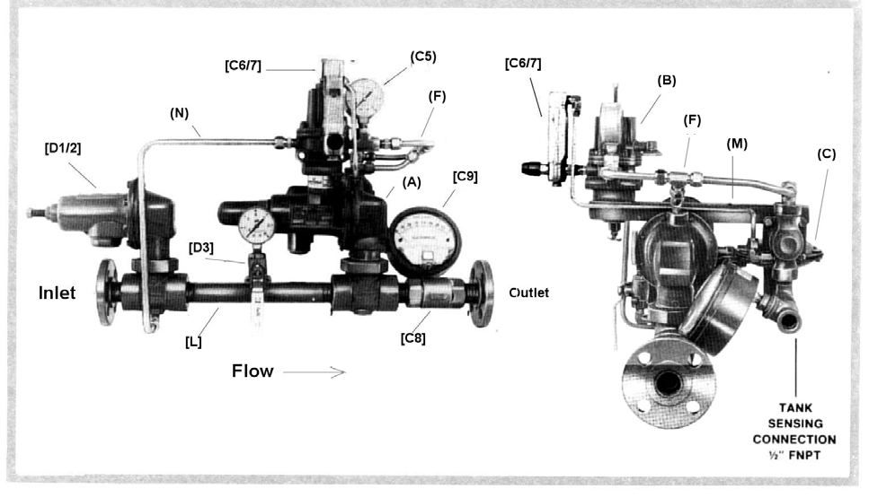
Parts Identification
NOTE | Letters/number in ( ) are standard features, numbers/letters in [ ] are options. |
(A) Main Control Valve
(B) Pilot Loading Regulator
(C) Sensing Regulator
(D) 1st Stage Regulator (Opt. D1 or D2)
[D3] Interstage Gauge & Shut-off Valve
(E) Orifice Tee
(F) Pilot Loading Tubing Manifold
(C5) Pilot Loading Pressure Gauge
[C6/C7] Sensing Line/Main Line Purge Meter
[C8] Outlet Check Valve
[C9] Tank Pressure Gauge
(L) Interstage Piping (Only on two stage Systems)
(M) Cross Bar
(N) Pilot Loading Regulator Supply Tube